The goal of this post is to consolidate some of the material from the extremely popular “Tesoro Golden Sabre Light TLSL” threads on the forums with hopes that it will encourage others to undertake this project and build confidence that could lead to a successful project.
While many have successfully completed this project, it is not recommended as a “beginners” project. It assumes that one has had basic exposure to electronics including component identification, good soldering skills and access to proper test equipment. While you tune the TGSL with only a multimeter, troubleshooting can be extremely difficult without an oscilloscope. The goal of this post is not meant to include every variation of the TGS but just one of the most popular. From there, the reader may learn and better understand how it works, how to setup, tune, troubleshoot, and extrapolate the difference in some of the other variations. I take no credit for what is documented here, other than that I made an attempt at the consolidation of information from the many members who have contributed. I only claim that the information posted here is accurate and correct. Complete details for this project including schematic, PCB layout, component placement, coil making and parts inventory will be added here.
Schematic diagram
The schematic can be broken down into about 12 functional blocks:
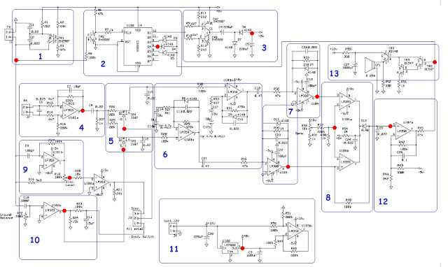
Bloc 1: The basic Colpitts oscillator. Together with the transmit coil attached to J1, it provides a 14.5 kHz low power Tx signal to the coil, audio circuit, -5v converter and a signal to use as a phase comparison for the receive circuit. Tx amplitude should be in the 16V range.
Bloc 2: The CD4024 is a binary counter that provides a clocking signal to the -5V converter, block 3. It also provides a synchronous audio signal to the audio driver, circuit block 13. The 14.5kHz signal from the oscillator is divided by 32 down to about 453Hz by the CD4024. Furthermore, the 3 diodes connected to pins 5, 6 and 9 work together create a very short duty cycle to save on audio power.
Bloc 3: Converts +8V to -5V to be used as a negative voltage source.
This test point may not be exactly -5V but should be relatively close.
Bloc 4: This is the Rx preamp, U101a. Keep in mind the output, pin 7 as we will see this one again! Also, C6 is very important as this tunes our Rx coil. C6 in parallel with the Rx coil tunes our Rx circuit to about 16.12 kHz (off resonance). This is required to get the proper phase relationships for disc and ground balance to work properly.
Bloc 5: TR4 and TR5 along with C12 and C15 make up our synchronous demodulators. They basically “gate” a sample of the the Rx signal by a phase related timing signal from block 9 (disc channel) and block 10 (ground balance channel ). Furthermore, C12 and C15 turn our sampled signal into a small D.C. value that varies with any phase shift from the Rx signal from block 4.
Bloc 6: U103a and U103b further amplify and filter our D.C. phase related signals. This functions as a bandpass filter with a frequency centered around 11Hz. This allows a low frequency pulse to pass to the next stage that should be in tune with the approximate sweep speed of the coil passing over a target, This is why proper sweep speed of the coil is important.
Bloc 7: Provides more D.C. amplification, filtering and limiting. Signals can be measured here as a D.C. Voltage that will swing + or – 1V or so as targets pass the coil. Keep in mind that U104 Pin 6 is the disc channel and U105 Pin 6 is the GB channel. Also, these test points can give a general indication of electrical “noise” in your environment. High noise levels can make your TGS perform poorly! In general, a measurement 5mV p-p of noise can be considered very good. 8.
Bloc 8: Here is where some interesting things happen that are not always obvious to the casual observer. Pins 2 and 6 are tied to a reference voltage and the LM393 compares the inputs on pins 3 and 5. The LM393 has the characteristic of being able to “sink” current from the opposite LM393 when the outputs are tied together. This type of IC is commonly referred to as an open collector design. So in order for the diode D12 to stop conducting (and ultimately provide forward bias for TR2 in block 13), BOTH U106 Pin1 and 7 must go high at the same time. Now in practice, the disc channel swings wildly as the loop is passed over the mineralized ground while the ground balanced channel only goes positive when the loop passes any type of metal. If the disc channel agrees with the ground balance channel at the same instant, we have detection! The voltage at the test point here should change from about .036V to close to 0v as the sensitivity pot is varied.
Bloc 9: Provides for positive phase adjustment to the reference signal for the disc channel.
Bloc 10: Provides for negative phase adjustment to the reference signal for the ground balance channel.
Bloc 11: +8V Voltage regulator circuit. TP 11 should test at 8V. Provides a D.C. bias signal to TR2 in block 13 upon target detection. Normally will be at about 6V and will drop to 0V as targets pass the coil
Bloc 12: Audio driver circuit. This test point varies from -5V to + Battery voltage as targets pass the coil
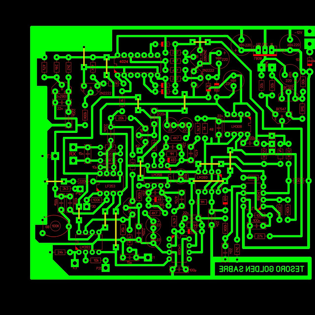
Circuit Construction
The information in the “ TGSL Complete Details.pdf” is accurate and repeatable and can be found here: http://www.geotech1.com/forums/showthread.php?t=15710 If a good PCB is made or purchased and attention to the documented component selection is adhered to, you should have little problem in reproducing a working circuit of your own. At the time of this writing. a slight variation in complete kit form (minus coil).
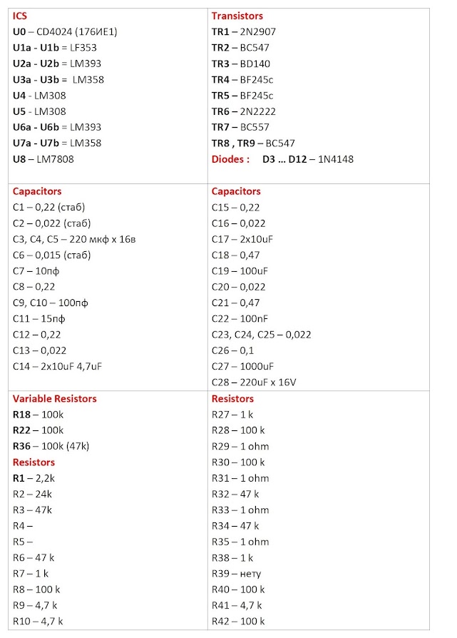
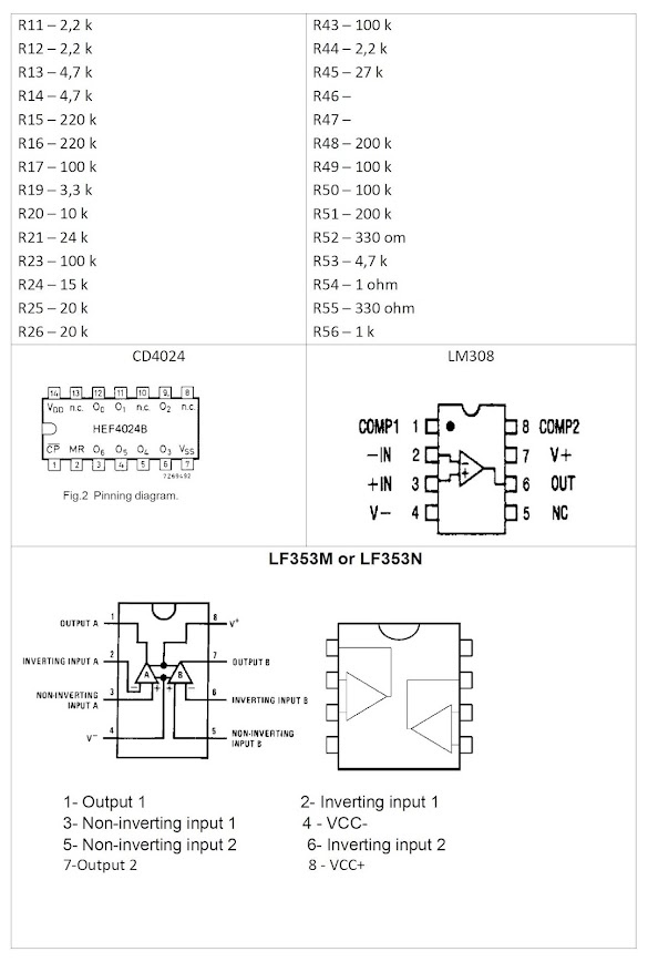
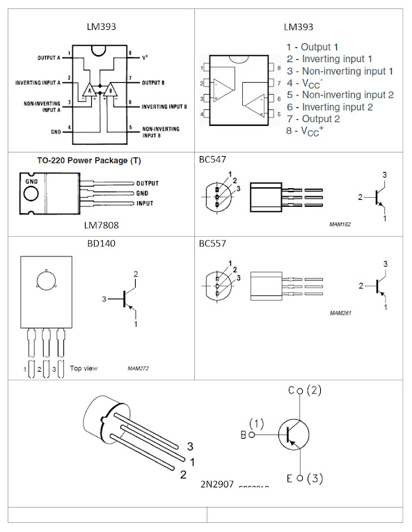
Components List:
It is highly desirable to have a tester that can measure the capacitance of capacitors. The matter is that in the device two identical channels of amplification, on it and amplification on them should go as much as possible identical, and for this purpose it is desirable to pick up those details which are repeated on each cascade of amplification so that they had as many parameters as possible. readings in a particular cascade on one channel - the same readings on the same cascade and in another channel).
In the process of making Golden Sabr found an extra function, which Ivkonik cut on Geotech. At the moment of setting BG (trimmer) on a piece of ferrite, you wave ferrite, you twist BG. There is a moment-ferrite is not visible. If BG is left in this position, then copper is not visible. And it turns out very convenient: I see well all the gold and silver rings, well, nothing more. No foil, no traffic jams, no walkers. If you then twist BG a little further, then honey appears. The first time I did, I set up from ferrite, and then adjusted the BG to the maximum for copper (as I do in Eldorado). Therefore, I missed this extra feature. And now it makes sense to bring BG to the panel and use it when you do not want to collect a walker. And if it squeaked, then it's exactly a ring of some kind. Well, I want to find a cross, turn off the discrimination regime.
Coil Construction & Tuning for Tesoro Golden Sabre Light TLSL
By far, coil making is the most challenging and will most likely determine the overall performance of the completed TGSL. Equally important is the final mechanical construction as the success of the project depends on it. Don't get discouraged though. With a little effort and attention to detail, it can be done! Of course an original coil for the Tesoro Golden Sabre can be purchased, but that would defeat our purpose. Besides, we can build one that outperforms the original!
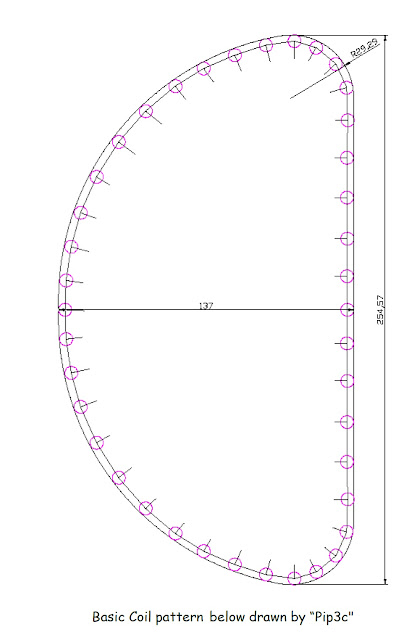
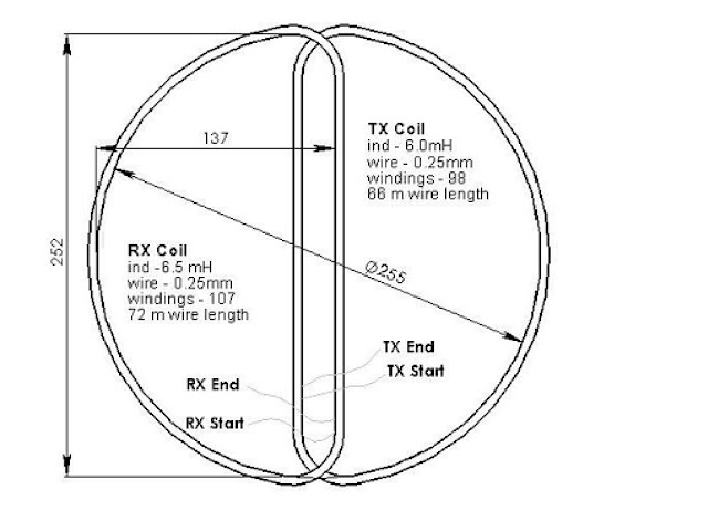
Below are the specifications for the most popular coil on the forums:
- Diameter: 255mm x 137 mm (one coil)
- Wire size: .25mm (30 AWG) enameled
- Tx inductance: 6.0mH
- Tx resistance: 18 – 25 Ohms
- Tx resonance - About 14.5 kHz
- Rx Inductance: 6.5mH
- Rx resistance 18 – 25 Ohms
- Rx resonance with 15nF – About 16.1 kHz
Regardless of the exact dimensions or number of turns, most importantly we must have the proper inductances and nulling or phasing will be off and proper ground balance setting and/or disc setting may not be possible. Before attempting to wind coils, we must have a way to measure or calculate inductance, operating frequency or both. Most commonly used are inductance meters, oscilloscopes or frequency counters. An alternate method will also be shown.
So, how many turns of wire? For this pattern, I am going to suggest 99 turns for Tx and 104 turns for Rx (30 AWG enameled wire). In running the calculations for coil inductances a difference of just 5 turns is usually the answer for difference of .5mH between the two coils. I have been able to consistently build “good” coils this way.
Due to variations in wire and pattern building, your number of turns needed to achieve proper inductances may vary. This is just a suggested starting point.
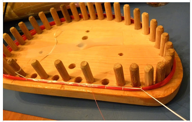
One method of winding on a form is depicted below. It's basically two slabs of wood clamped together and the holes for the pattern are drilled. Then wooden dowel pins are driven into the holes. Between the two halves, spacers are used to allow a uniform thickness (4mm) – about the thickness of 2 U.S. Nickels. You can use just one slab of wood and insert dowel pins but it is advantageous to use two sides for a number of reasons.
1. When winding a coil on a single sided form, it is more difficult to wind coils consistently and once constrained, inductances are far more likely change.
2. When winding a coil on a double sided form, turns can be easily added or removed to achieve the proper inductance before constraining.
Once wire is put on a form, it's a good time to verify inductance. This can be done with an inductance meter. Or.. my favorite method is just attach the coil to your completed circuit board (J1) and measure the running frequency. The Tx should run at 14.5 kHz.
Next, half of the form must be removed and the wire must be constrained. I use simple dental floss. Note: If wire is wound on a two sided form tightly, very little change in inductance will occur once constrained. At most, it should increase by only .1 mH.
Build your Rx coil in the same manner, except for the number of turns. Also, to check your Rx coil, you can attach it to your completed circuit as well, but attach your Rx coil to J1 (the Tx circuit). Since this is 6.5mH, the oscillator should now run at 13.95 kHz. Again, this is just a quick check and will then be removed!
Coil Shielding
Coil shielding is not optional. It is necessary to eliminate the effects of ground capacitance, static charges and to help eliminate noise from external electrical sources. The idea is for the coils to “see” the capacitance of the shields, which will be at the same potential as the circuit ground, and not earth ground, rocks or vegetation.
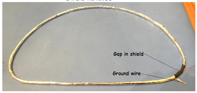
Choices for shielding material can be aluminum foil, aluminum, copper, or lead tape, “Scotch 24” shielding tape or metalized mylar (polyester film), just to name a few. Plain aluminum kitchen foil is usually the easiest to obtain and works just fine. I prefer metalized mylar as final sensitivity of the coil is noticeably better with this material. Sources of conductive mylar include mylar balloons, ribbons or bows from a party store, or reflective mylar survival blankets from a camping or outdoors shop. Keep in mind that in general, only ONE side of the mylar is conductive and must be in contact with any wires needed to attach to the cable ground! Once insulating is finished, you can apply shielding in the following manner:
1. Wrap a thin, bare wire on top of the electrical tape but stop about 1cm short of completing a full circle. Leave enough of a “pig tail” to solder to the cable ground.
2. Wrap one spiraling layer of aluminum or mylar around the coil, making sure that the conductive side (if using mylar) makes contact with the bare wire. Again, make sure to stop short of completing a full circle!
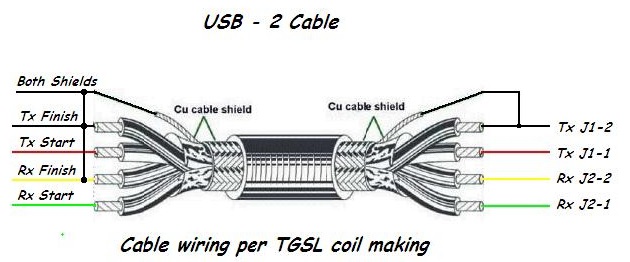
Cabling and Coil Grounding
There are several options when it comes to coil cabling. Below are just two methods that work well. While testing my first couple of coils, I was disappointed with the performance of the TGSL when the ground was wet. The bottom image is my preferred method of coil ground and offers improved performance in wet grass. Optionally, Use Belden-M (8723) cable.
Coil Nulling of Tesoro Golden Sabre Light TLSL
More controversy seems exists on coil nulling than any other aspect of this project. Basically, this is the process of overlapping the two coils so that they are in an “Induction Balance” state and the Rx coil will be under minimum influence of the alternating magnetic field of the Tx coil. This is because part of the Rx coil will be “inside” the Tx coil and part will be “outside” or part will see a positive magnetic flux and part will see negative flux at any instant in time. This may seem trivial, but I have seen so many new builders completely miss this concept.
Basic Nulling
To null coils, lay them out on a workbench free from the influence of any metal objects.
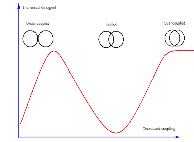
The final USB-2 cable to the circuit should be used and wires should be kept short as possible. Ideally, they should be placed inside the coil shells and the bottom coil should be secured. Power on the TGSL and adjust coil overlap while monitoring U101a, pin 7 with a DVM in the A.C. setting. The goal is to find a sharp null in the voltage between U101a pin 7 and the PCB ground . You should be able to get the signal down to about 4mV but the actual reading may be subject to the frequency response of the DVM used.
When you have found the deepest null while positioning the overlap of the coils, it is time to secure the coils mechanically and check the ground balance setting. For this, you will need a small ferrite slug scavenged from an old radio or possibly a toroid. Verifying correct circuit operation would very difficult without a ferrite slug! Start with the TGSL switched to the all metal mode and set the GB pot fully Counter Clockwise. Start waving the ferrite slug over the coil and advance that GB pot slowly Clockwise until the ferrite slug is rejected or the sound starts to break up. Advancing too much further and silver may be rejected in the DISC mode! This will be a good place to start for rejecting the return signal associated with ground. Possible problems: If ferrite cannot be rejected or accepted (in the all metal mode) at around the mid-range setting of the GB pot (or maybe just a little Clock wise of the mid-range setting) then possibly either the coils are not nulled or the difference in resonant frequency between Tx and Rx circuits is not correct (phasing is off).
Advanced Nulling Methods using 2-channels oscilloscope
1. Connect the “A” channel of scope to U103 pin 5. - Set scope to DC setting.
2. Set the GB pot to the mid range position.
3. Start with coils apart and start to overlap.
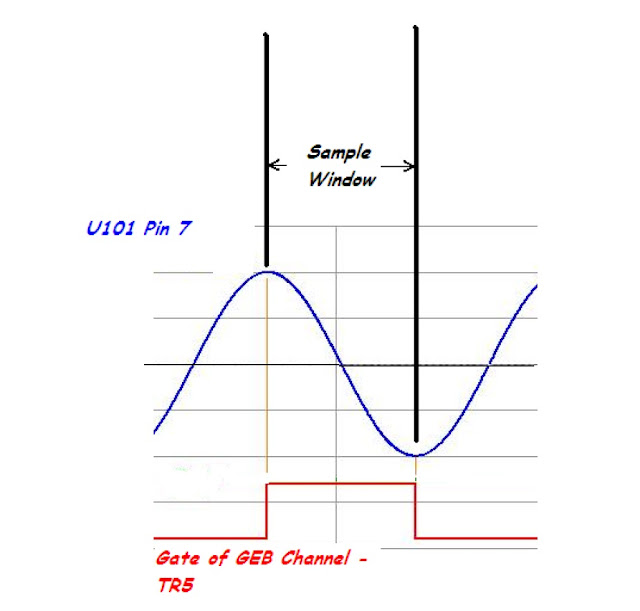
4. Continue increasing overlap until the the D.C. Signal on Pin U103 pin 5 is 0 volts. Check the phase relationship between J1-1 (Tx signal) against U101 pin 7 (Rx signal). If resonant frequencies are correct, the Rx signal will now be lagging the Tx signal by approximately 20º .(J1-1 and U101 Pin 7 traces)
Note: The Rx signal may not be at a minimum but should be very close to the null achieved in the “Basic Nulling” section above.
This is what is referred to as “Null phase” in the forums and corresponds to the sampling pulse from the Tx signal (gate of TR5) being centered on the zero crossing of the Rx signal coming from U101 pin 7.
The idea is, that at this setting, the influence of ideal ferrite on the Rx signal will be at a minimum – that is a slight change in signal amplitude caused by the “X” component of ferrite will have no effect. This is because any change in the positive and negative peaks of the sine wave would be equal and opposite and the net difference going into U103a would be 0. However, your ferrite sample is probably not ideal and neither is the ground, so we must still adjust the GB trimmer slightly to reject ferrite and ground. If nothing else, this procedure may help get the maximum range of adjustment from the GB potentiometer.
Dowloading files:


![[Arduino FreeRTOS tutorial] How to use semaphore and mutex](https://blogger.googleusercontent.com/img/a/AVvXsEjv4nInC0gGae_exqVbGJ3vHTe70Mt_3Tc2OTotIjgVpf3BPNJnmGYrvEYBxF3gUiDNfJl5IHSd-2ShuRFe7cR5AtsimzD6NZtmfCz-NNV1rLmvK3mw1yGjlMYCthIAOm3lz_vY7CTygjfPdmdR6fWtLJomA46NJOD8HGVMzLPK2mF9I9eE3VsJbQI=w72-h72-p-k-no-nu)


No comments:
Comments