
Metal detector PI Polonaise
Pi polonaise metal detector one of detectors which have a number of advantages over detectors working on a different principle. They include a large range, practically the same in the air and in the ground, very good sensitivity and complete insensitivity to changes in soil mineralization. The disadvantage is that it is not possible to discriminate between ferro and diamagnetic metals.

The schematic diagram of the pi polonaise detector is shown in Figure. The pi polonaise metal detector works on the principle of electromagnetic pulse emission into the ground. The presence of a metal object near the coil, as a result of a change in the inductance , causes voltage distortion on the coil. The signal from the coil is amplified and after cutting the interested fragment, it is amplified and integrated again. Processed in this way, it controls the VCO generator, the signal of which can be heard in the loudspeaker or in the headphones. The detector is made of several basic blocks. We will start the description of the principle of operation with the system for generating and stabilizing the supply voltages. It uses an unusual method of powering the analog part: the ground is connected to the positive pole of the detector's supply voltage. Therefore, obtaining a positive voltage for the analog part requires the use of a voltage boosting converter, which in the described system was implemented with the use of IC5 (NE555).
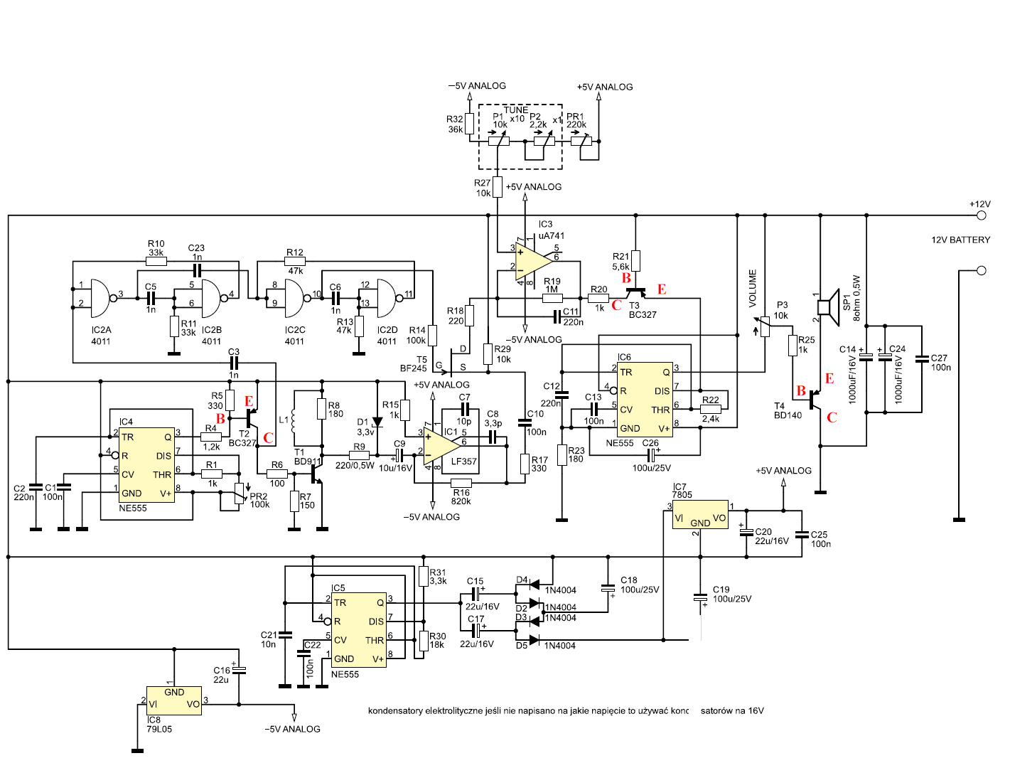 |
The inverter does not draw too much current, so it works in conjunction with the charge pump. In the first cycle, through the diode D4, the capacitor C15 is charged to the value of the supply voltage, and then (in the second cycle) the energy stored in it, through the diode D2, is transferred to the capacitor C18. As a result, the C18 capacitor is charged to a voltage almost equal to twice the detector's supply voltage. "Almost" because it is reduced by the voltage drops on the diodes D2, D4. The circuit with diodes D3, D5 and the capacitor C19 works similarly to the one described earlier, with the only difference that its input voltage is equal to the voltage on the capacitor C18. The entire converter duplicates the detector's supply voltage nearly three times.
Operational amplifiers are supplied with symmetrical voltage of ± 5 V. The stabilizers IC7 and IC8 are responsible for its stabilization in relation to the analog mass. Capacitors C4, C14, C24, C16, C19, C20, C25 filter the supply voltages. The square wave that powers the coil is generated by the second NE555 (IC4) circuit. The signal frequency is determined by the elements C2, R1, PR2. It should be approximately 100 Hz and the negative pulse at IC4 output should be approximately 150 ms long. The signal from the output IC4 through the resistor R4 controls the transistor T2, which inverts it in phase. Then, through the resistor R6, it drives the transistor T1 which powers the probe coil L1. The resistor R8 is designed to limit the self-induction voltage of the L1 coil. The signal from the probe, through the resistor R9 and the capacitor C9, goes to the inverting input of the operational amplifier IC1. The Zener diode D1 protects this input against overvoltage. To enable sampling of the amplified signal from the coil when it crosses zero, two monostable generators built on NAND gates contained in IC2 (CD4011) were used. Both generators are connected in a cascade. The first one, built on the gates IC2A and IC2B, generates a pulse with a length of 60 ms and triggers the second one, built on the gates IC2D and IC2E, generating a pulse with a length of 85 ms. The construction of both monostable generators, apart from the values of the R and C elements, is identical, so the principle of operation of only the first one is described below. At the start, the capacitor C5 is discharged. The falling edge of the voltage on the collector of transistor T2 causes an immediate change of the output state of the IC2A gate from logical "0" to "1". The capacitor C5 discharged so far begins to charge via the resistor R11. The charging current of the C5 capacitor forces the inputs of the IC2B gate to a high state, which causes the change of its output state to low, and thus maintains the low state at the IC2A gate inputs until the C5 capacitor is charged. A falling edge at the output of the first trigger triggers the second trigger. The positive pulse from the output of the second trigger is to open the transistor T5 and transfer via R17 and C10 the useful part of the signal to the inverting input of the integrator amplifier IC3.
Installation and start-up of the detector
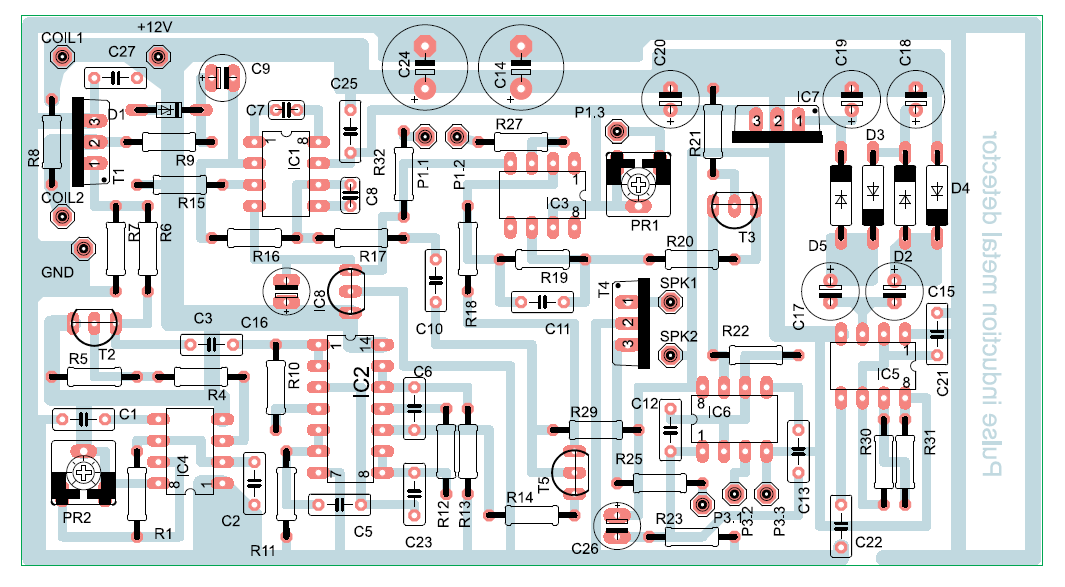
The assembly diagram is presented in Figure. Power on the detector with checking the correct operation of the power supply part. For this purpose, only the IC5, IC7, IC8, capacitors C4, C14, C24, C18, C19, C20, C25, C16, C21, C22 and the resistors R31 and R30 are soldered to the board. Then turn on the detector's power supply and check the presence of ± 5 V on pins 7 and 4 of IC1 and IC3. The measurement is made reference to the positive of power supply. After confirming the correct voltage values, assemble the elements of the coil signal generator (IC4, T1, T2, C1, C2, R1, R4, R5, R6, R7, R8 and the PR2). Connect the probe to the points marked on the PCB as "COIL1, COIL2" and turn on the power - we should hear a quiet buzzing of the probe. If we have a frequency meter or an oscilloscope, set the frequency of 100 ... 110 Hz on pin 3 of IC4. After these steps, we mount the remaining elements on the printed circuit board. Connect the volume control potentiometer to the points marked on the board as P3.1, P3.2, P3.3 using a piece of a three-wire ribbon, and tuning potentiometers to points P1.1, P1.2, P1.3. The next step will be to turn the volume knob as far as it will go towards the output of IC6. Place the detector probe in such a way that it is moved away from any metal objects to a distance of at least 1 m. Set the coarse and fine tuning potentiometers on the detector panel to the middle position and gently turn the PR1 potentiometer. We set the loudspeaker knocking frequency to about 0.5 ... 2 Hz. After these activities, we check the detector's reaction to bringing metal objects closer to the coil. A properly made detector clearly signals the presence of a shoe polish can from a distance of about 0.4 ... 0.5 m. It is best to use a 12 V gel battery to power the detector. Due to the large current consumption of the detector (approx. 100 mA), use a battery with a capacity of at least 1 VAh.
Part-list
The entire detector frame was built using basic tools such as: drill, coil, saw. Therefore, there should be no problem with making the detector at home. 1/2 ”diameter plastic water pipes were used as the basic building material. The structure of the frame allows to disassemble it into two parts, and also - if necessary - to quickly disassemble the probe. When unfolded, the detector easily fits into a car trunk, backpack or bag.

Coil construction
We will need about 16 m of insulated copper wire with a diameter of 0.5 ... 0.6 mm. The wire is wound on a circle with a diameter of 30 ... 40 cm. After the entire 16 m of wire has been wound, the coil is wrapped with a strong string so that its cross-section is circular. The next step is to saturate the coil with varnish. While the varnish is drying, place the coil between two planes (load the upper one). To make the coil housing, it is best to use a thin glass-epoxy laminate (of course copper-free), from which we cut two rings with an outer diameter larger than the diameter of the wound coil by about 3 cm.


![[Arduino FreeRTOS tutorial] How to use semaphore and mutex](https://blogger.googleusercontent.com/img/a/AVvXsEjv4nInC0gGae_exqVbGJ3vHTe70Mt_3Tc2OTotIjgVpf3BPNJnmGYrvEYBxF3gUiDNfJl5IHSd-2ShuRFe7cR5AtsimzD6NZtmfCz-NNV1rLmvK3mw1yGjlMYCthIAOm3lz_vY7CTygjfPdmdR6fWtLJomA46NJOD8HGVMzLPK2mF9I9eE3VsJbQI=w72-h72-p-k-no-nu)


No comments:
Comments