

Pulse metal detector "Pirate"
Recently, such an activity as the search for various old coins, household items, and just metal trinkets in the ground with the help of a metal detector is gaining great popularity. In fact, what could be better than walking in the morning across the field, breathing in the scents of nature, enjoying the views. And if at the same time it is possible to find some worthwhile find in the ground - it's generally a fairy tale. Some people do this on purpose, scouring fields all day long in search of valuable coins or other jewelry. They have at their disposal expensive factory metal detectors, which not everyone can afford to buy. However, it is quite possible to assemble a full-fledged metal detector yourself.
This article will focus on the creation of the most popular, demanded, time-tested, reliable pulse metal detector called "Pirate". It allows you to find coins in the ground at a depth of 15-20 cm and large objects at a distance of up to 1.5 m. The diagram of the metal detector is presented below.
Diagram metal detector "Pirate"
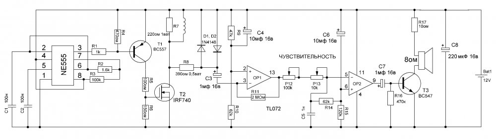
The whole circuit can be roughly divided into two parts - a transmitter and a receiver. The NE555 microcircuit generates square-wave pulses, which are fed to the coil through a powerful field-effect transistor. When the coil interacts with the metal next to it, complex physical phenomena occur, due to which the receiving part has the ability to "see" whether there is metal in the coil area or not. The microcircuit-receiver in the original scheme of the "Pirate" is the Soviet K157UD2, which is now becoming quite difficult to get. However, instead of it, you can use the modern TL072, while the parameters of the metal detector will remain exactly the same. The printed circuit board proposed in this article is designed specifically for the installation of the TL072 microcircuit (they have different pinouts).

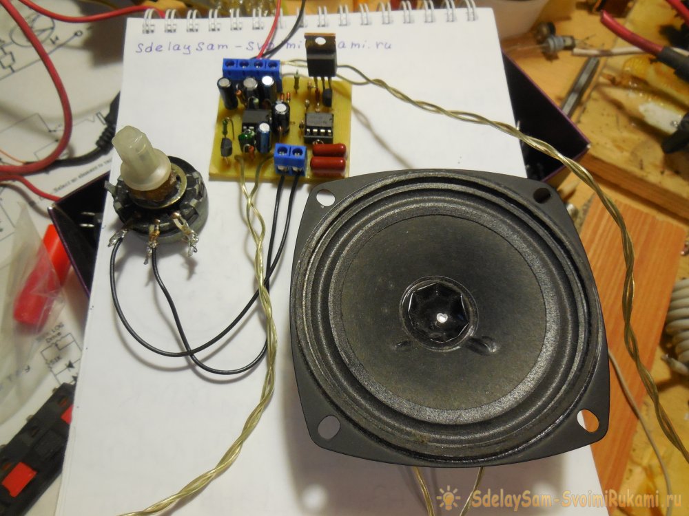
The speaker in the circuit is connected in series with a 10-47 ohm resistor. The lower its resistance, the louder the sound will be and the higher the consumption of the metal detector. Transistor T3 can be replaced with any other low-power NPN transistor, for example, the domestic KT3102. Any speaker can be used, the first one that comes across. So, let's move from words to deeds.
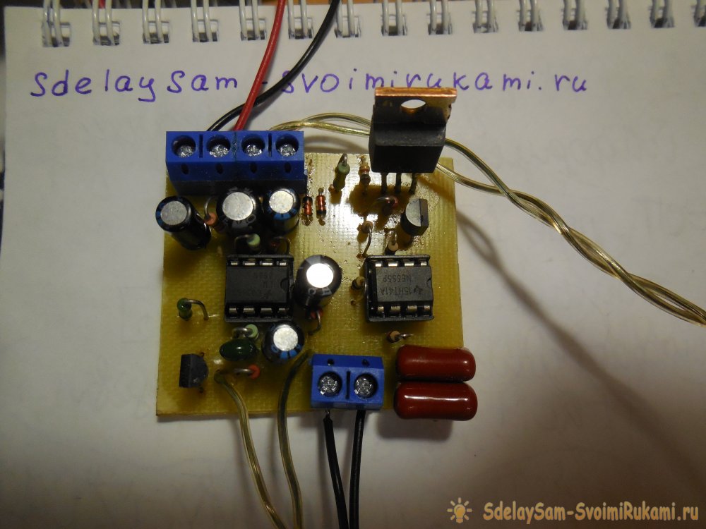
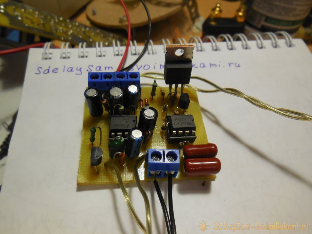
Assembling the metal detector
List of required parts
Microcircuits:- NE555 - 1 pc.
- TL072 - 1 pc.
- BC547 - 1 pc.
- BC557 - 1 pc.
- 100 nF - 2 pcs.
- 1 nF - 1 pc.
- 10 μF - 2 pcs.
- 1 μF - 2 pcs.
- 220 μF - 1 pc.
- 100 kOhm - 1 pc.
- 1.6 kOhm - 1 pc.
- 1 kOhm - 1 pc.
- 10 Ohm - 2 pcs.
- 150 Ohm - 1 pc.
- 220 Ohm - 1 pc.
- 390 Ohm - 1 pc.
- 47 kOhm - 2 pcs.
- 62 kOhm - 1 pc.
- 2 MOhm - 1 pc.
- 120 kOhm - 1 pc.
- 470 kOhm - 1 pc.
- Speaker 1 - pc.
- Diodes 1N4148 - 2 pcs.
- DIP8 sockets - 2 pcs.
- Potentiometer 100 kOhm - 1 pc.
- Potentiometer 10 kOhm - 1 pc.
Printed circuit board
The printed circuit board is made using the LUT method, you do not need to mirror it before printing.
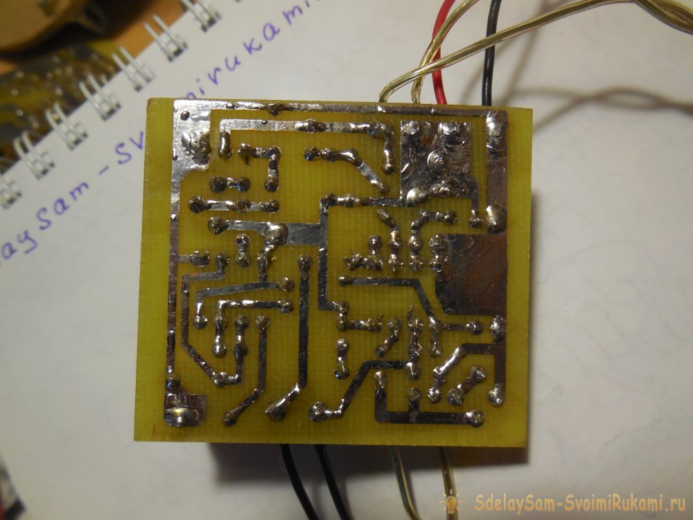
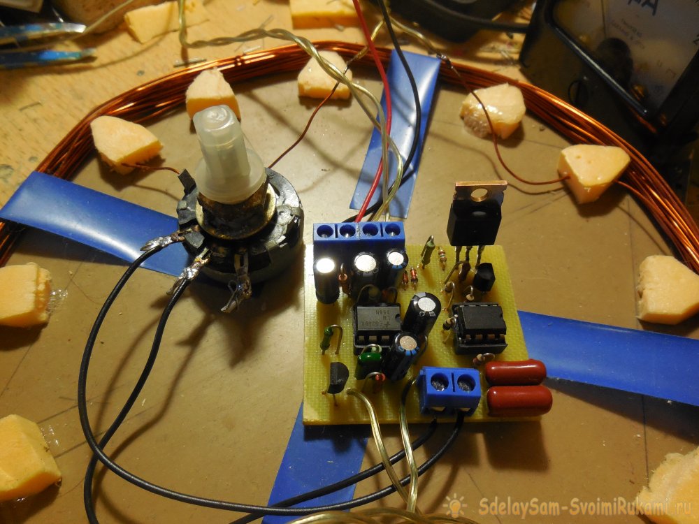
First of all, you need to solder resistors, diodes to the board, then everything else. It is advisable to install the microcircuits in the sockets. The wires for connecting the coil, speaker, potentiometer and coil can be soldered directly into the board, but it is more convenient to use screw terminal blocks, then it will be possible to connect and disconnect the wires without using a soldering iron.

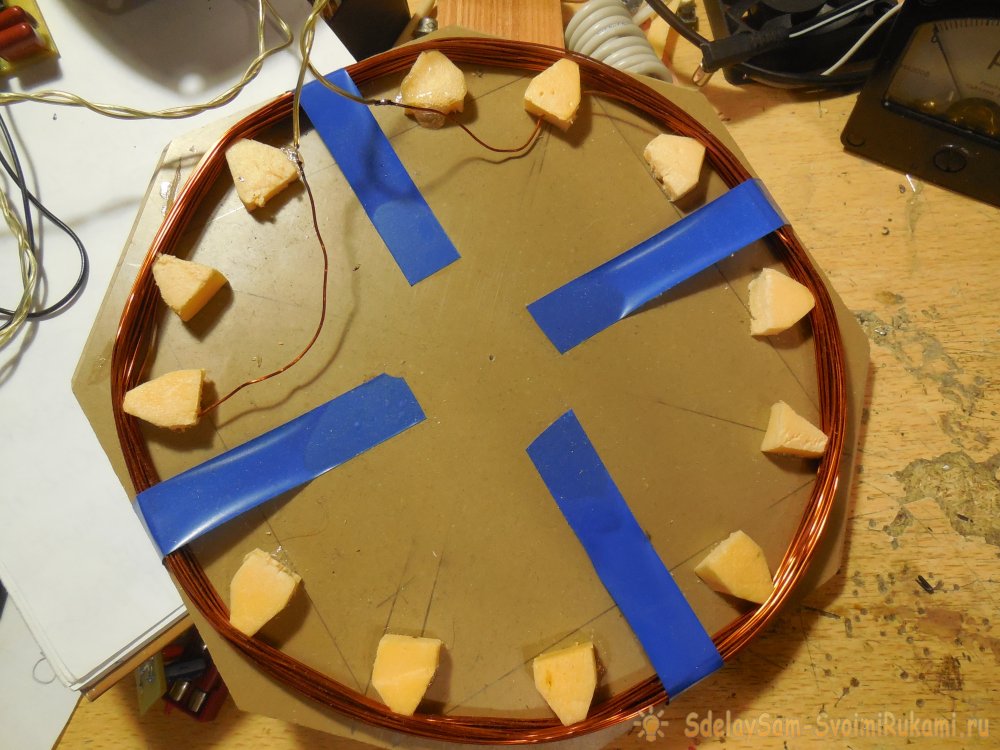
Making a coil
A few words about the search coil. The best option is to wind 20-25 turns of copper wire with a cross section of 0.5 mm2 on a round frame with a diameter of about 20 cm.The sensitivity to a large extent depends on the number of turns, so you should first wind more turns, about 30 pieces, and then, gradually decreasing the number of turns , choose the number at which the sensitivity will be maximum. The wires from the board to the coil should not be long, preferably copper and with a cross section not less than the cross section of the coil wire.

Setting up a metal detector
After assembling the board, winding the coil, the device can be turned on. In the first 5-10 seconds after switching on, various noises and crackling will be heard from the speaker, this is normal. Then, when the operational amplifier enters its operating mode, you need to find a mode with a potentiometer when individual clicks will be heard from the speaker. When a metal object is brought to the coil, the frequency of clicks will increase significantly, and if the metal is brought into the very center of the coil, the trust will turn into a continuous hum. If the sensitivity is not enough, and changing the number of coil turns does not help, it is worth trying to select the values of the resistors R7, R11, changing them up or down. The board must be cleaned of the flux, it often causes the metal detector to malfunction. Successful assembly!


![[Arduino FreeRTOS tutorial] How to use semaphore and mutex](https://blogger.googleusercontent.com/img/a/AVvXsEjv4nInC0gGae_exqVbGJ3vHTe70Mt_3Tc2OTotIjgVpf3BPNJnmGYrvEYBxF3gUiDNfJl5IHSd-2ShuRFe7cR5AtsimzD6NZtmfCz-NNV1rLmvK3mw1yGjlMYCthIAOm3lz_vY7CTygjfPdmdR6fWtLJomA46NJOD8HGVMzLPK2mF9I9eE3VsJbQI=w72-h72-p-k-no-nu)


No comments:
Comments