

stepper motor is a brushless DC motor that can rotate in steps and is the best choice for many precision motion control applications. In addition, stepper motors are suitable for positioning, speed control, and low-speed applications that require large torque.
In the previous MATLAB tutorial, we have introduced how to use MATLAB to control DC motors, servo motors and household appliances. Today we will learn how to use MATALB and Arduino development board to control stepper motors. If you are new to MATLAB, it is recommended that you learn to use MATLAB to start a simple LED blinking program.
Working mode of stepper motor
Before starting the relevant code of the stepper motor, you should understand the working or rotation concept of the stepper motor. Since the stator of the stepping mode is composed of different coil pairs, each coil pair can be excited in many different ways, which enables the mode to be driven in many different modes. The following are relatively broad categories:
● Full Step
In the full-step excitation mode, we can achieve a complete 360° rotation with the smallest number of turns (step size). But this will cause the inertia to decrease and the rotation will not be smooth. There are also two categories in the full-step excitation, which are a phase-turned square wave stepping mode and two phase-turned square wave stepping modes.

1. One phase step or waveform step: In this mode, only one terminal (phase) of the motor will be energized at any given time. This has fewer steps, so a full 360° rotation can be achieved. Due to the small number of steps, the current consumption of this method is also very low. The following table shows the waveform step sequence of a 4-phase stepper motor
2. Two-phase step: As the name of the method indicates, two phases will be one step. It has the same number of steps as the waveform step, but since two coils are energized at a time, it can provide better torque and speed compared to the previous method. But one disadvantage is that this method also consumes more power consumption.
● Half-step mode
The half-step mode is a combination of one phase-on mode and two phase-on modes. This combination will help us overcome the above shortcomings of the two models.
As you may have guessed, because we are combining the two methods, we will perform 8 steps in this method to get a complete rotation. The switching sequence of 4-phase stepper motors is shown below:
Therefore, you can choose to program the stepper motor in any mode, but I prefer the two-phase stepper mode. Because this method provides faster speed than the single-phase method, and because the number of steps in the two-phase method is smaller compared to the half mode, the amount of code is less.
Create MATLAB graphical user interface for controlling stepper motors
Then we must build a GUI (graphical user interface) to control the stepper motor. To start the GUI, type the following command in the command window
A pop-up window will open, and then select the new blank GUI as shown in the figure below,

Now select the two toggle buttons for clockwise rotation of the stepper motor and counterclockwise rotation, as shown in the figure below,

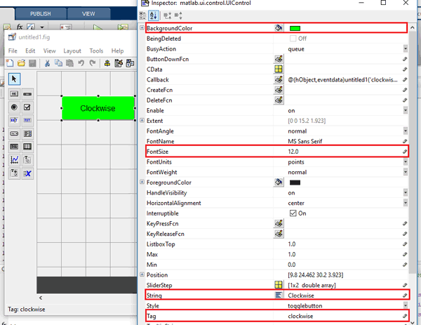

You can customize the buttons according to your choice. Now when you save it, a code is generated in the Editor window of MATLAB . To code the Arduino to perform any tasks related to the project, you always have to edit this generated code. So below we edited the MATLAB code. You can learn more about the command window, editor window, etc. in the MATLAB Getting Started tutorial.
MATLAB code for controlling stepper motor using Arduino
The complete MATLAB code for controlling the stepper motor is given at the end of this article. In addition, we include the GUI file (.fig) and code file (.m) here for downloading (right-click the link and select "Save link as..."), use it to customize the button according to your requirements. Below are some adjustments we made using the two toggle buttons to rotate the stepper motor clockwise and counterclockwise.
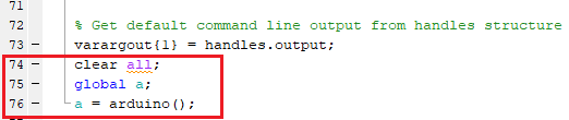
Copy and paste the following code to 74 lines of code to ensure that Arduino is communicating with MATLAB every time you run the m file.
As you scroll down, you will see that two functions have been created for the two buttons in the GUI. Now write code in the two functions according to the task to be clicked.
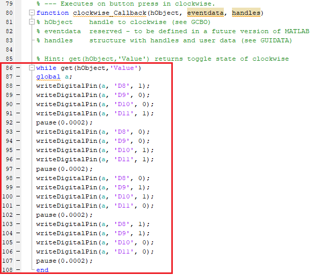
In the clockwise button function, copy and paste the following code at the end of the function to make the motor rotate clockwise. In order to continuously rotate the stepper motor clockwise, we use a while loop to repeat the two phase stepping full mode steps in the clockwise direction.
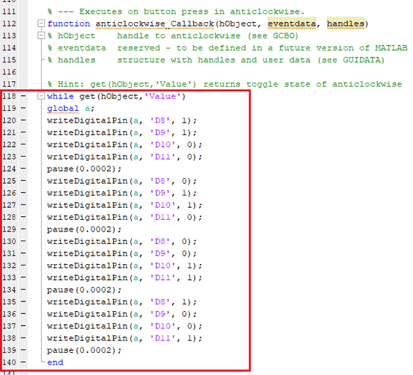
Now in the function of the counterclockwise button, paste the following code to the position of the function to rotate the motor in the counterclockwise direction. In order to continuously rotate the stepper motor in the counterclockwise direction, we use a while loop to repeat the two phase stepping full mode steps in the counterclockwise direction.
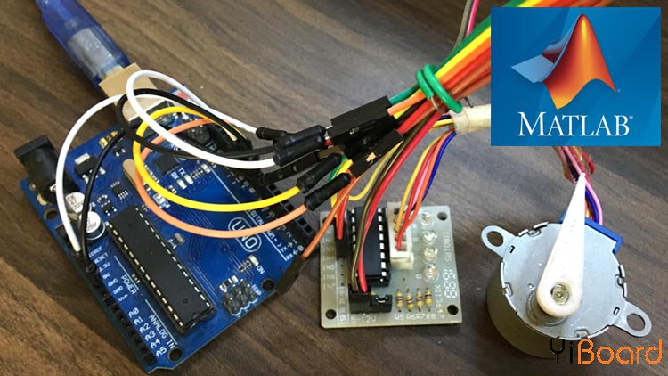
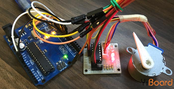
Required materials
● Install MATLAB on laptop
● Arduino UNO development board
● Stepping motor (28BYJ-48, 5VDC)
● ULN2003-Stepper Motor Driver
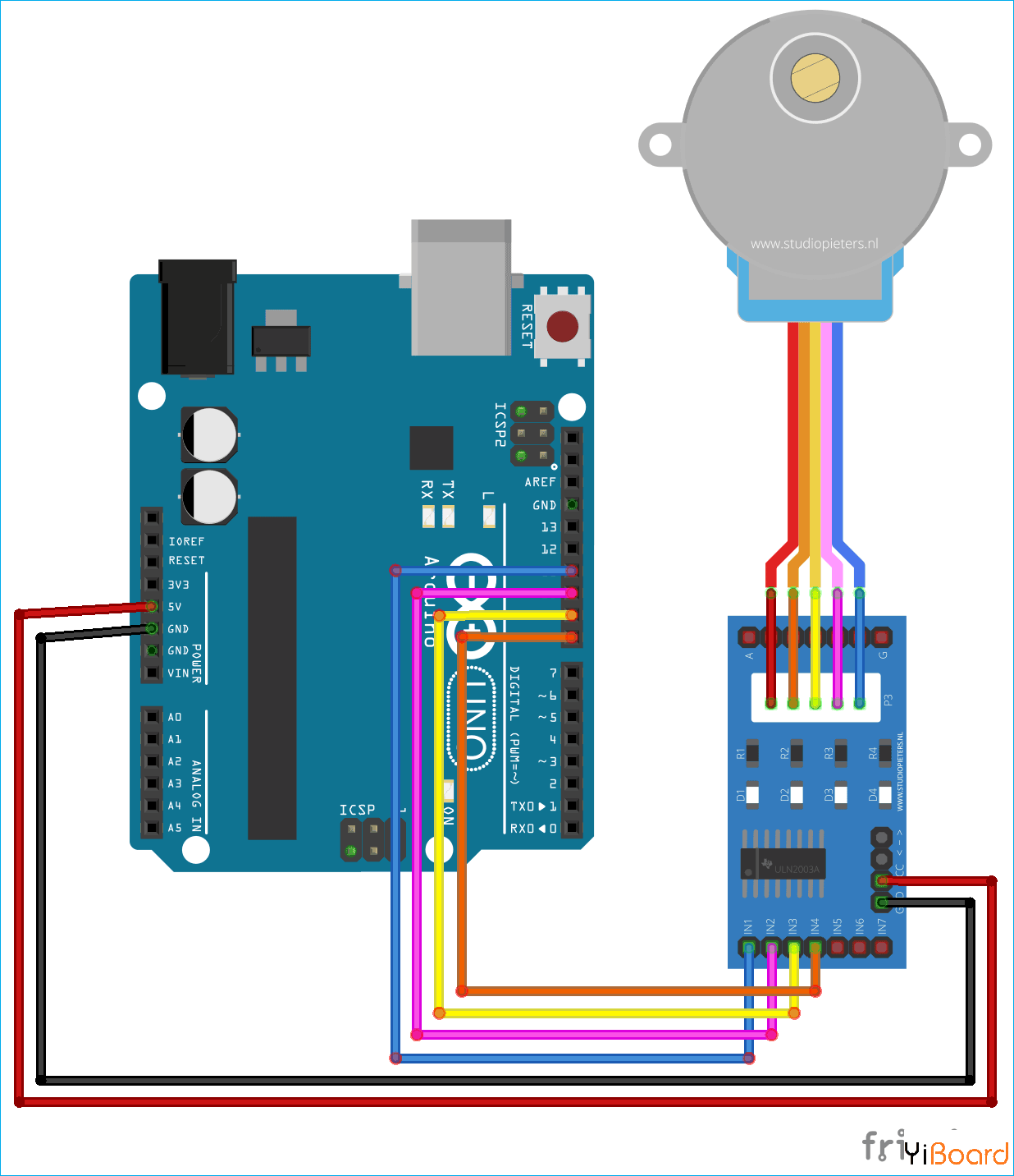
Circuit schematic
Use MATLAB to control stepper motor
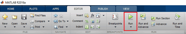
After setting up the hardware according to the circuit diagram, just click the run button to run the edited code in the .m file
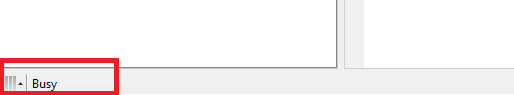
MATLAB may take a few seconds to respond, do not click any GUI buttons until MATLAB displays a busy message in the lower left corner, as shown below,
When everything is ready, turn the motor clockwise or counterclockwise by pressing the button. When we use the switch button, the stepper motor will move continuously in a clockwise direction until we press the button again. Similarly, pressing the counterclockwise switch button, the motor starts to rotate counterclockwise, until we press the button again.
Complete Code
The complete code for this article is as follows:
function varargout = untitled1(varargin)
gui_Singleton = 1;
gui_State = struct('gui_Name', mfilename, ...
'gui_Singleton', gui_Singleton, ...
'gui_OpeningFcn', @untitled1_OpeningFcn, ...
'gui_OutputFcn', @untitled1_OutputFcn, ...
'gui_LayoutFcn', [] , ...
'gui_Callback', []);
if nargin && ischar(varargin{1})
gui_State.gui_Callback = str2func(varargin{1});
end
if nargout
[varargout{1:nargout}] = gui_mainfcn(gui_State, varargin{:});
else
gui_mainfcn(gui_State, varargin{:});
end
function untitled1_OpeningFcn(hObject, eventdata, handles, varargin)
function varargout = untitled1_OutputFcn(hObject, eventdata, handles)
varargout{1} = handles.output;
clear all;
global a;
a = arduino();
function clockwise_Callback(hObject, eventdata, handles)
while get(hObject,'Value')
global a;
writeDigitalPin(a, 'D8', 1);
writeDigitalPin(a, 'D9', 0);
writeDigitalPin(a, 'D10', 0);
writeDigitalPin(a, 'D11', 1);
pause(0.0002);
writeDigitalPin(a, 'D8', 0);
writeDigitalPin(a, 'D9', 0);
writeDigitalPin(a, 'D10', 1);
writeDigitalPin(a, 'D11', 1);
pause(0.0002);
writeDigitalPin(a, 'D8', 0);
writeDigitalPin(a, 'D9', 1);
writeDigitalPin(a, 'D10', 1);
writeDigitalPin(a, 'D11', 0);
pause(0.0002);
writeDigitalPin(a, 'D8', 1);
writeDigitalPin(a, 'D9', 1);
writeDigitalPin(a, 'D10', 0);
writeDigitalPin(a, 'D11', 0);
pause(0.0002);
end
function anticlockwise_Callback(hObject, eventdata, handles)
while get(hObject,'Value')
global a;
writeDigitalPin(a, 'D8', 1);
writeDigitalPin(a, 'D9', 1);
writeDigitalPin(a, 'D10', 0);
writeDigitalPin(a, 'D11', 0);
pause(0.0002);
writeDigitalPin(a, 'D8', 0);
writeDigitalPin(a, 'D9', 1);
writeDigitalPin(a, 'D10', 1);
writeDigitalPin(a, 'D11', 0);
pause(0.0002);
writeDigitalPin(a, 'D8', 0);
writeDigitalPin(a, 'D9', 0);
writeDigitalPin(a, 'D10', 1);
writeDigitalPin(a, 'D11', 1);
pause(0.0002);
writeDigitalPin(a, 'D8', 1);
writeDigitalPin(a, 'D9', 0);
writeDigitalPin(a, 'D10', 0);
writeDigitalPin(a, 'D11', 1);
pause(0.0002);
end


![[Arduino FreeRTOS tutorial] How to use semaphore and mutex](https://blogger.googleusercontent.com/img/a/AVvXsEjv4nInC0gGae_exqVbGJ3vHTe70Mt_3Tc2OTotIjgVpf3BPNJnmGYrvEYBxF3gUiDNfJl5IHSd-2ShuRFe7cR5AtsimzD6NZtmfCz-NNV1rLmvK3mw1yGjlMYCthIAOm3lz_vY7CTygjfPdmdR6fWtLJomA46NJOD8HGVMzLPK2mF9I9eE3VsJbQI=w72-h72-p-k-no-nu)


No comments:
Comments